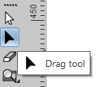
The EasySIGN node editing toolbar offers a wide selection of features to alter your vector designs. You can add or delete, move, shape and redesign your vectorlined objects. Select a vector object in your worksheet and press on the Drag tool in the toolbox on the left side of your EasySIGN worksheet:
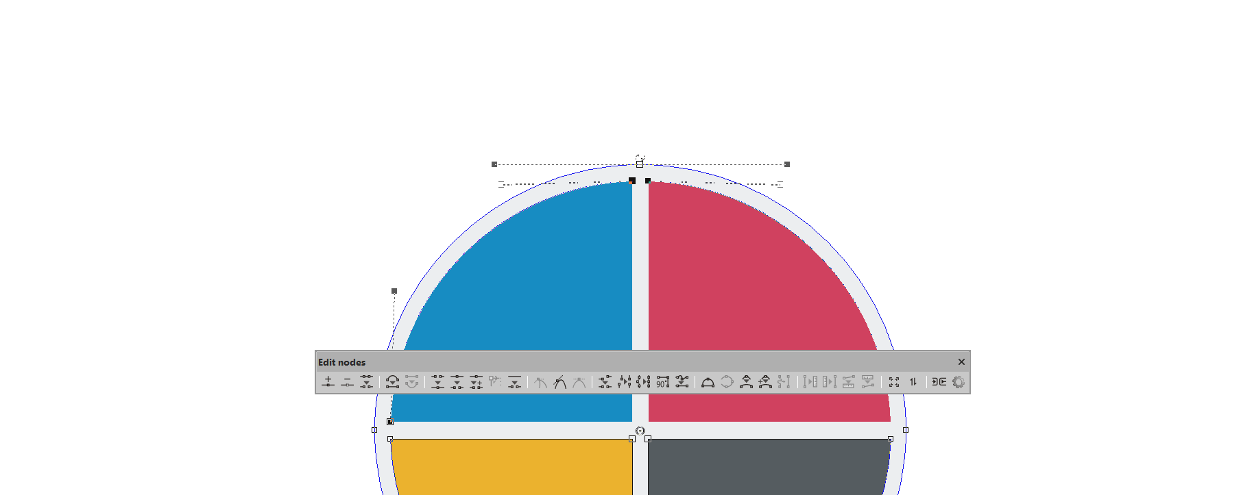
The node editing toolbar will open after pressing on the black arrow.

The following tools are present in the Edit nodes toolbar:
1. Add node: Select this tool and the drag tool will appear with a + alongside. A node will be added on any part of the line you click.
2. Delete node: Select the node you want to delete and press this Delete node button.
3. Delete vector: Select the line you want to delete and press this Delete vector button.
4. To line: Select a curved line and transform this into a straight line.
5. To curve: Select a straight line and transform this into a curved line.
6. Join: Select two nodes and join them to one single node.
7. Break: Break a single node into two separate nodes.
8. Break and move: Break node(s) into two separate nodes while moving the nodes.
9. Set startpoint: Set the startpoint of the shape. This is where your plotter (or other output device) will start cutting the shape.
10. Open Shape: Open a line and add nodes. When you use this tool the drag cursor will be displayed with a pair of scissors alognside it.
11. Make sharp: Make a sharp node. This is a node where only one handle will be edited, the adjoining handle is not influenced.
12. Make smooth: Both handles of the node will change simultaneously, except when you change the length, in that case the adjoining handle will remain unchanged.
13. Make symmetrical: Both handles of the node will change simultaneously at the same lenght.
14. Align horizontal: Align all selected nodes to a horizontal line.
15. Align vertical: Align all selected nodes to a vertical line.
16. On one line: All selected nodes will be placed on a line between the first and last selected node.
17. 90 degree angle: The selected nodes will be placed at a right (90 degrees) angle.
18. Replace by line: Make a straight line of all selected line parts between the first and the last node.
19. To arc: When you open this tool the drag cursor will add an "arc" alognside. You can draw now an arch from any type of line.
20. Averaging points on a curve: Manually adjust the smoothness of a curve.
21. Smoothen corner: Smoothen the corners of a line manually.
22. Smoothen corner at specified radius: Set the corners of a line with a radius.
23. Replace by curve: Convert a selection of nodes into one curve.
The following tools are used for transferring the lenght and/or angle from one curve on another
24. Measure ref. lenght:: Measure the lenght of a curve.
25. Apply ref. lenght:: Apply the lenght on a curve.
26. Measure ref. angle:: Measure the angle of a curve.
27. Apply ref. angle:: Apply the angle on a curve.
28. Scale: Manually resize the selected curve.
29. Rotate/Skew: Rotate or skew the selected curve.
30. Mark as Bridge: Convert a node into a bridge which can be used for engraving and routing applications to prevent the design from falling out.
31. Settings: Press on this button to open the Dragtool settings menu
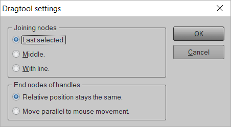
You can set the position for:
Joining nodes: Choose Last selected to connect to the last selected node, or Middle to connect to the middle position or With line to draw a line between the selected nodes.
End nodes of handles: Choose Relative postion stays the same when moving a line the relative postion between the nodes handles stays the same or choose Move parallel to mouse movement in that case the relative position between the node handles will change according the position of the mouse.
You may also like

Color Management