When for example engraving nameplates or milling a letter mold, it is required to run your production without errors and avoid additional expensive material costs. Keep control on a flawless output with the routing and engraving features in EasySIGN. A selection of the reliable production tools as present in the EasySIGN Premium license, are collected in this tip & trick.
Lead in
When milling a job the routing tool has to reach speed and depth in the material to archieve a smooth routing result. Adding a Lead in prevents from dents in the beginning or at the corners of your routed design. The tool will take a lead in path to reach the optimal production condition before arriving at the object. You can set the Lead in properties in the Tool path options menu.
Drill holes
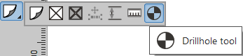
Add a drill hole with the Drill hole button in the EasySIGN toolbox on the left side of your EasySIGN worksheet. Change the depth or size of the drillhole in the Tool path options menu.
Rotate toolpath direction
Arrange > Rotation direction > Reverse rotation direction
Decide what is the optimal tool rotation direction and change this, in case needed, by swapping the begin and end point of a tool path. With this feature you can choose between conventional milling and down milling.
Convert toolpaths
Edit > Convert to > Toolpath to curves
Converting the toolpaths to curves in order to export the file to process the routing file in another production software, for example the CNC software of the router.
Set start point
After converting the toolpath to curves you can alter and set the start point of the toolpath with the Node editing tool.
Bridges
Bridges are a helpfull tool to avoid material from moving when the object is routed. Bridges can be added directly in the toolpath menu

or with the Node editing after the toolpath is converted into curves.
Optimize for inlay
Edit > Optimize for inlay...
This is a media saving feature by avoiding loss of engraving or routing materials due to an incorrect tool selection. Select your production object and open the Optimize for inlay... menu. Choose a tool from the tool library and preview if the tool is suited for producing your design. In case the diameter of the tool is too large the preview on screen will display an incorrect result.
You can set the tool or choose a Diameter to be used for production. Choose for a Male or Female production and Mirror the results.
Male: The path will be run outside the object. The actual shape of the object will be the result.
Female: The path will be run inside the object. The actual shape of the object will be removed from the material.
You may also like

Color Management